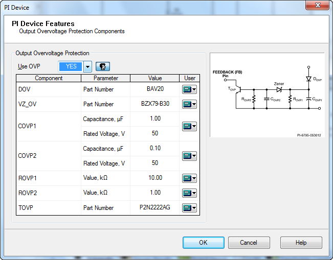
The PI Device Features OVP form displays the calculated values related to secondary overvoltage protection.
This optional circuit will protect the power supply if the LED string becomes an open circuit. By default PI Expert will keep this circuit off, and it is up to the user to turn it on. You can turn on using overvoltage protection by selecting Use OVP checkbox.
For LNK-PL this is a relatively simple circuit because the topology is non-isolated flyback. It is possible to directly measure the output and the Zener diode provides an accurate protection. As soon as the feedback voltage hits the Skip Cycle threshold (check datasheet for the exact value) the PI Device will stop switching.
For LNK-PH the overvoltage protection uses the bias voltage to indirectly measure the output voltage. A separate rectifier is used (DOVP + COVP1) in order to avoid the long time constant of the feedback rectifier circuit. Once the voltage across COVP1 is higher than the Zener diode voltage plus the base-emitter voltage of the transistor TOVP, it will short the feedback pin, causing a latching shutdown. ROVP1 and ROVP2 ensure that the capacitors are discharged when the power supply is off, and ROVP1 also guarantees that there will be no peak charging across COVP1.
You can change the overvoltage protection components by clicking the calculator icon ![]() on the right of each component in the overvoltage protection components box. The dialog boxes where you can select another component will be displayed as the following:
on the right of each component in the overvoltage protection components box. The dialog boxes where you can select another component will be displayed as the following:
The Diode dialog box - for diode.
The Zeners dialog box - for zener diode.
The Capacitor dialog box - for the capacitor.
The Resistor dialog box - for the resistor.
The Transistor dialog box for the rectifier damper.
Select the component you want to add, or edit the resistor parameters when changing the resistor. Click OK.
The ![]() icon indicates that a custom parameter value has been entered. Click the icon and select Default to restore the default automatically selected value.
icon indicates that a custom parameter value has been entered. Click the icon and select Default to restore the default automatically selected value.