The Core and Bobbin dialog contains information about the transformer core and bobbin and allows you to change core and bobbin parameters. Note that you can enter custom core and bobbin parameters right within the spreadsheet using the appropriate cells. These custom core and bobbin parameters will be used where applicable. Specifications that are not available directly through the spreadsheet are located in the Core and Bobbin dialog.
The following parameters and parameter groups are available:
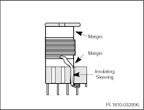
Insulating tubing is used to insulate the start and finish leads of windings in a margin wound transformer to meet required safety creepage distances. The margin is an area of the transformer bobbin-winding window purposely filled with non-conductive material to increase bobbin creepage distance.

Sleeving is typically used with magnet wire transformer construction. The tubing should be recognized by the applicable safety agencies. The tubing should also be heat resistant, so it does not melt when exposed to temperatures required to solder transformer lead wires. Materials commonly used for sleeving are Teflon tubing or heat shrink tubing. Sleeving is also necessary if foil windings are used in the transformer design. Now, for the maximum standard AC input voltages of 230 VAC, transformer bobbins need to have a 3.2 mm safety pedestal for the secondary side pins. If such transformer bobbin is used, sleeving is not necessary.
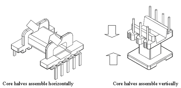
Horizontal and Vertical bobbins are classified according to the orientation of the core halves with respect to the PCB. The figure below shows pictures of a horizontal bobbin (left) and how the core halves assemble horizontally (parallel to the PCB). Similarly, it can be seen how in a vertical bobbin (right) the core halves assemble vertically (perpendicular to the PCB):

To edit the default value click the calculator icon ![]() on the right of the Maximum termination per pin box . The
on the right of the Maximum termination per pin box . The ![]() icon indicates that the custom parameter value is specified. Depending on the wire size that is used for the windings to be terminated on each pin, you might have to decrease the number of windings to be terminated on each pin so that it is possible to actually build the designed transformer. If the wire sizes are too large, terminating many windings on a single pin can be very difficult and non-repeatable.
icon indicates that the custom parameter value is specified. Depending on the wire size that is used for the windings to be terminated on each pin, you might have to decrease the number of windings to be terminated on each pin so that it is possible to actually build the designed transformer. If the wire sizes are too large, terminating many windings on a single pin can be very difficult and non-repeatable.
You can set the default value for maximum terminations per pin under the Preferences Transformer Defaults tab.
To edit the parameters in the Core and Bobbin Information group, click the calculator icon ![]() . The
. The ![]() icon indicates that the custom parameter value is specified.
icon indicates that the custom parameter value is specified.
The following parameters are available:
Core Type - displays the core type value.
Default Core Material - You can enter a custom ferrite material in this box.
Bobbin Reference - You can type the bobbin part number or a description.
Number of Primary and Secondary pins used - By default PIXls Designer will calculate the minimum number of pins required for the design of a transformer. PIXls Designer can not check if such bobbins are available. Check with your magnetics vendor to find a bobbin with the minimum number of pins on primary and secondary side as calculated by the software. You can increase the number of pins manually to match the bobbin availability from vendor in the Pin Allocation tab.
Margins on Left (Bottom) and Right (Top) - If these fields are available for editing, you can specify the margins to include in your transformer design.