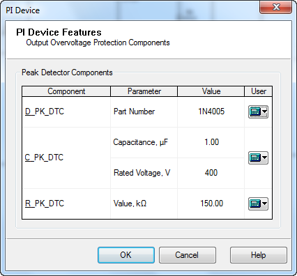
The PI Device Features Peak Detector form displays the calculated values related to the peak detector circuit.
By default the software will use the same values for the peak detector, independently of line voltage, output power, or dimming configuration.
The peak detector circuit is used to provide a DC voltage from which current is fed into the V pin of the LinkSwitch-PH device. Resistor R_PK_DTC provides a discharge path so that the voltage across the capacitor C_PK_DTC tracks the AC voltage. For C_PK_DTC a value of at least 100nF should be used in order to achieve a power factor of 0.9. Optimum values can usually be achieved with 1uF; however a larger value may help the system during surge by absorbing part of the energy.
PI Expert constructs peak detector components configuration automatically when creating a design.
You can change the peak detector components by clicking the calculator icon ![]() on the right of each component in the peak detector components box. The dialog boxes where you can select another component will be displayed as the following:
on the right of each component in the peak detector components box. The dialog boxes where you can select another component will be displayed as the following:
The Diode dialog box - for the diode.
The Capacitor dialog box - for the capacitor
The Resistor dialog box - for the resistor
Select the component you want to add, or edit the resistor parameters when changing the resistor. Click OK.