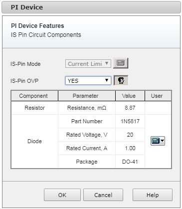
The ISpin circuit form displays secondary Current Sense Pin Mode and Overvoltage Protection availability through ISpin. Three modes are available for InnoSwitch3 families.
None - If secondary current sense is not required, the ISpin is connected to the secondary ground pin.
Current Limit - An external current sense resistor is connected between this pin and the secondary ground pin (the default mode for single output design).
Protection - Requires common ground for all outputs. (Default mode for multiple stacked output design).
See Technical Reference for more details.
You can turn on using ISPin overvoltage protection through ISpin by selecting YES in ISPin OVP drop-down box.
Diode is set between ISPin and secondary ground pin or in parallel to the resistor depending on ISPin mode. It is typically used to detect an overvoltage and activate overvoltage protection mechanism.
To replace diode component click the black down arrow control on the right of the calculator icon ![]() and select Change. In the Diode dialog box, select the diode you want to add. Click OK. The diode is now replaced. The
and select Change. In the Diode dialog box, select the diode you want to add. Click OK. The diode is now replaced. The ![]() icon indicates that the custom selected diode is chosen. To restore the default diode click the black down arrow control on the right of the
icon indicates that the custom selected diode is chosen. To restore the default diode click the black down arrow control on the right of the ![]() icon and click Default.
icon and click Default.
The resistor value is calculated automatically.