IS Pin Circuit
a) b)
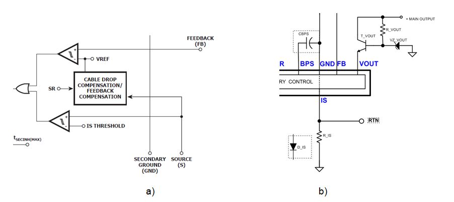
Figure1
The IS pin is a comparator input with a 35mV threshold as shown in Figure1 a.
The pin can be used to provide:
1. CC regulation – single output only
Where the InnoSwitch-3 comprises an internal bond wire connecting the IS and GND, this wire is used as an internal sense resistor to regulate the output current (Figure1 b). The output current is trimmed to achieve 1A, 1.5A, and 2A (referred to as Io in the electrical parameter table).
The internal bond wire has a limited fuse current rating. The wire I2t rating could be exceeded if an output comprising a large output capacitance, charged to high output voltage, is shorted. To limit the peak voltage across the bond wire during such a fault condition and prevent irreversible damage to the wire, an external diode must be connected across the IS-GND pins.
Higher power InnoSwitch-3 devices have a TRIM OPTION, which uses an external current sense resistor R_IS instead of an internal bond wire. Similarly, a small Schottky diode (20V, 1A) could be connected between the IS and GND pins to limit the peak voltage at the IS pin during a fault condition.
2. Overcurrent protection – single output only
Where CC regulation is not required, but over-current protection is desired the resistance R_IS is chosen such that 20% margin above the max continuous output current is provided. The converter therefore needs to be designed thermally so that it can sustain the power dissipation while working at 20% above its continuous power rating.
3. Generic power limit – multiple output design
In a multiple-output design, the load currents of all outputs flow through the current sense resistor R_IS. Therefore only a very general power limit will be facilitated. Its actual level will depend on the load combination of all individual outputs. No individual output will have guaranteed over-current protection. Note that negative outputs will have their load currents flowing through R_IS in reverse direction.