|
Notification 227 - High output ripple current: High ripple, low ESR Capacitors required |
||
|
CATEGORY |
ISSUE / RESULT |
FIX / REFERENCE(S) |
|
Information |
One or more output capacitors will be required to decouple high ripple currents (IO 4.0 A). Therefore, the ripple current capacity and ESR of the output capacitors used on those outputs should be verified before considering this design manufacturable. Subjecting Aluminum Electrolytic capacitors to excessive ripple current can reduce their expected life span significantly and lead to premature aging and failure. |
|
Various high-ripple current rated Aluminum Electrolytic capacitor manufacturers and model numbers |
||||
|
Manufacturer |
Type |
Capacitance / Voltage / Temperature |
Size (¢DxL) |
Max Temp., 100 kHz Ripple Rating (Irms) |
|
Panasonic |
FC |
1000 mF / 35 V / 105 °C |
12.5 x 25 mm |
1945 mA |
|
|
HFQ |
1000 mF / 35 V / 105 °C |
12.5 x 30 mm |
1950 mA |
|
United Chemicon - Marcon |
LXY |
220 mF / 25 V / 105 °C |
8 x 12 mm |
555 mA |
|
|
LXZ |
220 mF / 25 V / 105 °C |
8 x 15 mm |
555 mA |
|
Nichicon |
PF |
560 mF / 35 V / 105 °C |
12.5 x 20 mm |
855 mA |
|
|
PL |
560 mF / 35 V / 105 °C |
12.5 x 20 mm |
1430 mA |
Table 1. Various high-ripple current rated capacitors and their ripple current ratings; see also Component Listings.

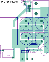
Figure 1. Proper layout with consistent path lengths and trace widths (equal impedance) to four (4) output capacitors.