The Z factor indicates the proportion of losses between the primary and secondary, and is defined as secondary-side losses divided by the total losses of the supply:

Thus 0 < Z < 1. A value close to 1 indicates that the majority of the losses are on the secondary side of the power supply, and a value close to 0 indicates that the majority of the losses are on the primary side of the power supply.
Z factor is important because together with efficiency it determine the actual power that must be processed by the primary power components (primary Switch and transformer). Therefore, the value of Z affects the value of the transformer's primary winding inductance, the size of the transformer, the primary Switch operating mode (continuous or discontinuous conduction) and even the EMI performance of the power supply.
When considering the components that dissipate power so that their loss can be categorized as either primary-side or secondary-side losses, their identification as primary or secondary side has more to do with what part of the switching cycle (switch on or switch off) the losses occur during, more so than what side of the primary-to-secondary isolation barrier the components are installed on.
EMI filter + Input Rectifier: the significant loss occurs here due to the input current that flows while the rectifier diodes are conducting. Since the associated energy loss is not stored in the inductor, this is a primary-side loss.
Primary Switch Conduction loss: occurs during the primary Switch ON time and is, thus, a primary-side loss.
Primary Switch Switching loss: this is a complicated loss to assign to either the primary or the secondary sides. The turn-on losses are properly attributed to the primary side, but the turn-off losses can technically be attributed to the secondary side. Since the primary Switch turn-off losses are typically greater in magnitude than turn-on losses, a conservative approach would be to assign them to the secondary side
Transformer Node Drain capacitance: drain-node capacitance loss occurs primarily during primary Switch turn ON when power in being processed by the switch, and energy is being stored in the primary inductance of the transformer, making it a primary-side loss.
Transformer Copper loss: losses due to the flow of current through the primary winding of the transformer are primary-side losses.
Output Cable Loss: since all power delivered to the output comes from energy is stored in the transformer, any dissipation of that power in secondary side components is accounted for as a secondary-side loss.
Bias Winding Power: since the Bias winding is an output that conducts during the primary Switch OFF time, it is a secondary-side loss.
Primary-Side Clamp: the equivalent circuit of the primary-side clamp makes it an output circuit since it is only active (dissipating power) when the primary Switch is off. The energy that it dissipates is stored in the transformer, which makes it a secondary-side loss.
Transformer Core Loss: core losses are independent of switch on or off time. The energy dissipated within the core is processed by the inductance of the transformer primary winding. Therefore, it is considered a secondary-side loss.
Output Rectifier and Snubber: rectifier losses occur during MOSFET OFF time while the diode is conducting, which causes the snubber capacitor across the diode, if present, to charge. However, most of the snubber loss occurs when the MOSFET turns on, which discharges the snubber capacitor. However, since the energy that has been used to charge the capacitor initially is processed during the MOSFET OFF time, it is still a secondary-side loss.
Transformer Copper Loss: the losses due to the flow of current through the secondary winding of the transformer are secondary-side losses.
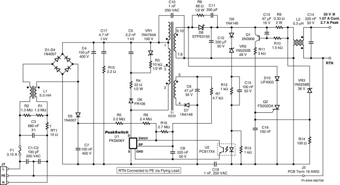
The prototype shown in the figure below has been run at 88 VAC input and at 29 V, 2.42 A output (70.18 W). Total input power was measured as 93.2 W, giving an overall efficiency of 75.3%. That means that the total losses in the power supply, PLOSS, were 23.02 W.

The following are the prominent areas where losses can be categorized as Primary side losses. All other losses will therefore be secondary-side losses.
We need the following parameters to calculate each of the above mentioned losses. The values in parentheses are the value that was measured for each of the parameters.
Primary RMS current, IRMS (1.42 A)
Primary Switch Duty ratio, D (0.68)
Primary Switch RDSON, RDSON (2.6 W)
Diode conduction time, tC (3.75 ms)
Switching frequency, FSW (299 kHz)
Line Frequency, FL (60 Hz)
Common mode inductor wire resistance, RCM (0.7 W)
Transformer primary winding resistance, RPW (0.5 W)
Bulk capacitor ESR, RESR(0.8 W)
Primary Switch Switching transition time, DT (48 ns)
Primary Switch Switching Voltage, VSW (269 V)
Primary Switch Switching Current, ISW (2.42 A)

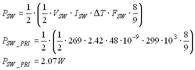
The Primary Switch switching loss is difficult to allocate as a primary side or secondary-side loss. It affects both sides of the transformer and yet it is a significant loss element. We will therefore allocate half the losses to primary side and the other half to the secondary side.

Figure 1. Scope plot showing the Drain current (top) and the Drain Voltage (bottom).
It can be observed from Figure 1, that this power supply skips one out of every nine switching cycles to maintain output regulation. This must be factored into the total switching losses.

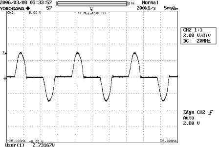
Since there are two windings in common mode inductors, its loss is multiplied by two. TC is the diode conduction time. For this supply, TC was measured as 3.75 ms (see figure 2).

Figure 2. Input diode (current) conduction time: 3.75 ms


The total Primary Side loss, PLOSS_PRI is therefore:
PLOSS_PRI = PCOND + PSW_PRI + PEMI + PDIODE + PCOPPER + PESR
PLOSS_PRI = 8.2133 W
Thus, the total secondary-side losses PLOSS_SEC can be written as:
PLOSS_SEC = PLOSS - PLOSS_PRI
PLOSS_SEC = 14.81 W
By the definition of Z factor:
