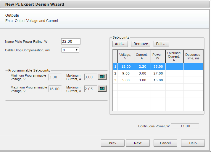
By means of the Output specification wizard the user can specify the number of set-points, output power, and cable drop compensation which characterize the design.
The first step is to define the Nameplate power of the power supply.
For USB PD and USB PD + PPS application, once the user has inputted the Nameplate power, PI Expert will automatically compile the list of baseline set-points which the power supply is required to advertise by the USB PD standard.
In case of USB PD + PPS application, along with the minimum number of set-points, the programmable voltage range, defined by Minimum and Maximum programmable voltage, is automatically defined.
For custom rapid charger application, the user is responsible to specify each set-point to satisfy the custom requirements.
Once the baseline set-point and the standard programmable range (Only for USB PD + PPS) are automatically added, the user can easily add, remove or modify the number of set-points as well as the value of voltages and currents. Please note that this may cause the design not to be standard compliant.
To add a set-point the user must click the Add… button.
To remove an existing set-point the user must firstly select the set-point to delete and then click the Remove button.
To modify an existing set-point the user must first select the set-point to amend and then click the Edit… button.
When adding or modifying a set-point, the Output Dialog opens up. Please refer to the specific help topic for more information on how to interact with this wizard.
All the Set-points are shown in the summary table. Voltage, current and power is displayed for every Set-point. The two additional fields, Overload Current and Debounce time allow the user to specify the possible overload condition that the power supply may be required to deliver during a particular set-point operation. Over load Current identifies the magnitude of the Overload current; the Debounce Time is expressed in ms and identifies the duration the overload condition is required to last for.
When no overload condition is inputted for one or more set-point, the two fields, Overload current and Debounce time are simply blank.
Programmable Set-Points
These fields are only enabled when USB PD + PPS or Custom rapid Charger application is selected.
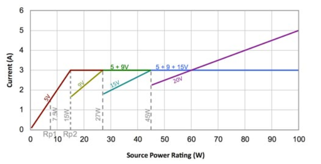
For USB PD + PPS as briefly described above, once the user inputs the nameplate power (PDP Rating), PI Expert automatically fills in the programmable range which is required in order to satisfy the USB PD Standard.
Minimum Programmable voltage = 3.3V (constant)
Maximum Programmable voltage: the value depends on the maximum nominal voltage.
The table below summaries the concept expressed by the standard
|
Fixed nominal voltage |
||||
|
5V Prog |
9V Prog |
15V Prog |
20V Prog |
|
| Maximum Voltage |
5.9V |
11V |
16V |
21V |
| Minimum Voltage |
3.3V |
3.3V |
3.3V |
3.3V |
The current fields are calculated as follows:
Maximum current @ Minimum Programmable voltage = Maximum current between all the set-points
Maximum current @ Maximum Programmable voltage = Nameplate power (PDP)divided by Maximum Programmable voltage, the resulting value is rounded down to the nearest 10mA
The user can overwrite the programmable fields by clicking the user input icon.
Note: Modifying the values of Minimum and Maximum programmable voltage may cause the power supply not to be standard compliant.
Outputs
The output dialog allows the user to define the key parameters of each set-point:
Voltage, V
Current, A
Overload current, A
Debounce Time, ms
Voltage and Current define the nominal condition at which the power supply will be designed to operate in steady state.
The resulting power is automatically calculated every time the user modifies either the Voltage of Current field.
Overload current and Debounce time allow the user to specify the overload condition which the power supply may be required to correctly function for a limited duration.
The Overload current identifies the magnitude of the current (higher than the nominal current) which may be required for a time frame equal to the Debounce Time expressed in ms.
Standard values for the Overload current are 110% or 120% of the nominal current.
If no Overload conditions are required, both fields must be set to 0.
PI Expert only accepts both fields to be either zero or non-zero. Any otherwise assignment will result in an error.