When selecting a MOSFET for synchronous rectification, please note the following:
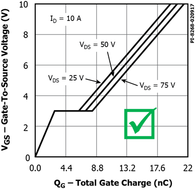
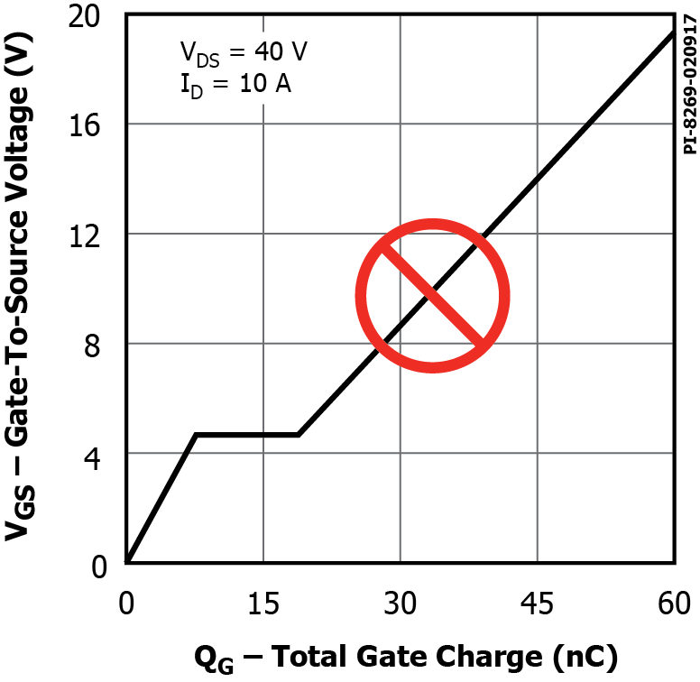
1. 1.The InnoSwitch3 SR gate drive pulse has 4.4V amplitude. It is therefore recommended that the gate threshold voltage, VGS(th), of the SR MOSFET be well below that level for proper drive. See Figure 1 below:
Figure 1: Gate-Source voltage as a function of turn-on gate charge
2. 2. It is strongly recommended that MOSFET datasheets should provide parameter values such as RDS(ON) for VGS of 4.5V. See example in Figure 2 below.
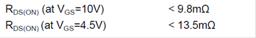
Figure 2 Datasheet example showing RDS(ON) with 4.5V gate voltage
3. 3. When selecting the SR MOSFET, make sure that under normal operating conditions, the device voltage rating, VDS, has at least 20% margin above the maximum reverse voltage across the MOSFET drain and source terminals for the corresponding winding, as shown by Equation 1 below.
![]()
Equation 1: Device VDS rating
Here VAC_RMS_MAX is the maximum specified mains voltage, NSEC is the transformer secondary number of turns, and NPRI is the primary number of turns.
Note that for a similar MOSFET die size, increasing the voltage margin (selecting MOSFET with a higher VDS rating) may normally result in a higher RDS(ON), hence increased conduction loss. The alternative is to use a larger die (more expensive) MOSFET for the synchronous rectification.
4. If synchronous rectifiers are used in more than one output, these outputs must be referenced to the same point. Consequently, the source terminals of the two SR MOSFETs should both be connected to that point.
5. The Source and the Gate terminals of the synchronous rectifier should have short connecting traces to the GND and the SR pins respectively.