The Solutions Filter dialog box allows the user to adjust the optimization parameters during the optimization process, therefore influencing the optimization process to produce design result which are more in line with the user final goal and/or preferences.
The Solutions Filter dialog box is always displayed at the beginning of the optimization process if the Show Solutions Filter check box is selected in User Preferences, Design Defaults.
You can turn the Solutions Filter dialog box on or off only for the current design by using the Show Solutions Filter check box in the Default design form.
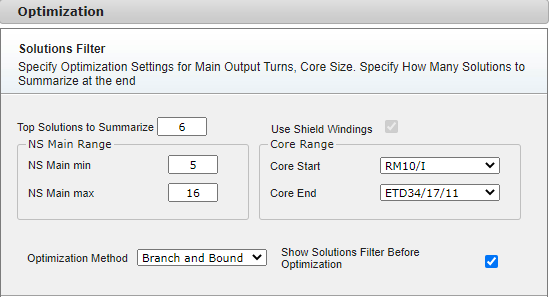
Figure 1: Optimization solution Filter dialog
You can adjust the following basic parameters using the Solutions Filter form:
• Top Solutions to Summarize - The number of the design solutions PI Expert displays when optimization is complete.
• NS Main Range (NS Main Min - NS Main Max) - Enter a range of turns for the main output to be used during optimization. Choosing a large range can present different solutions at the end of the optimization process, however the optimization will take longer to complete. Core Range - Select the cores to be used during optimization. Cores are arranged in order of increasing power output. See Transformer Selection and Manual Design for more information.
• Optimization Method – Both optimization methods search for the best among all designs that satisfy the design requirements. The best designs are selected by assigning a score that accounts for estimated efficiency, transformer sizing and component selection. The following optimization methods are available:
• Branch and Bound – Iteratively narrows down available ranges of design parameters
• Exhaustive Search – Searches overall combinations of design parameters
• Show Solutions Filter before Optimization - Select if you want to display the Solutions Filter dialog box for the active design
•
For InnoSwitch3 families and LightSwitch6 family you can access further optimization settings by clicking on the Chevron Arrow “Advance settings” as shown in the figure 2:
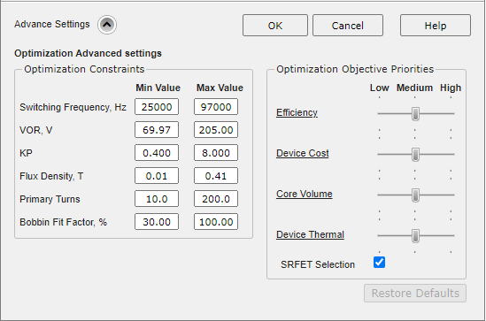
Within the advanced settings you can modify the optimization constraints and/or the Optimization objective priorities.
Figure 2: Optimization advanced settings
Optimization constraints.
The optimization Constraints are the maximum and minimum bounds of the optimization parameters such as, Switching Frequency, VOR, KP, Maximum Flux density, number of Primary Turns and set a threshold of acceptance for the bobbin Fit Factor (the percentage of the bobbin height occupied by the windings). The Optimization will attempt to find one or more solutions which satisfy these constraints. If the optimization does not find a solution, it may help relax the constraints.
By default, the optimization attempts to finds a balanced solution is terms of efficiency, transformer Size and cost and thermals of primary switch and secondary rectifier.
By means of the sliders placed in this section, you can now set three incremental levels of priority (Low, Medium, and High) to each of the objective function terms. For example, if the highest level of priority is given to the efficiency term, you can expect a more efficient design which in turn might use a more expensive controller and/or SRFET. On the contrary if the highest priority is given to cost and the lowest priority to all the other terms, you can expect a resulting design which presents a cheaper device as well as a cheaper SRFET. This will result in a more cost effective design with some impact on overall efficiency or thermal performance.
If no Synchronous rectification is used, then the checkbox is set to false and disabled by default.