![]()
For each active design PI Expert provides a Transformer Construction. It gives all the necessary information and specifications to build the transformer that has been designed. It also allows the user to edit the transformer parameters.
Transformer Construction contains 6 blocks. You can minimize, maximize, resize, change the position of each block. User can open toolbar to operate with the blocks by mouseover on the Show button  in the lower right corner.
 -hide/show Mechanical Diagram block.
 -hide/show Electrical Diagram block.
 -hide/show Winding Info block.
 -hide/show Coil/Coil Former Parameters block.
 -hide/show Winding Parameters block
 -hide/show Building Instructions block.
 -Reset all blocks position to default.
Mechanical diagram
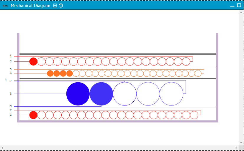
Mechanical Diagram displays the mechanical drawing of the transformer. The drawing provides information on the winding order, the direction of windings, start and termination
pins, and the number of parallel wires (filars) to be used for each winding. The mechanical diagram is scaled in proportions to actual coil former dimensions. The circles on the
diagram represents the actual number of turns multiplied by the filar and actual wire diameter in proportions to coil former size. Some circles are filled with color.
It represents the mechanical start of the winding. Also, number of filled circles represent number of filars. Windings are marked with different colors depending on the type.
User can change the color of his choice. By default, red is primary power winding, blue is secondary power winding, green is shield winding, orange is bias winding.
Interleaved windings are displayed by alternating circles of different colors.
User can operate with windings on the Mechanical Diagram via drag and drop functionality.
By dragging and dropping one winding over another context menu will open. User can select to set winding to interleave, to swap winding or to clear interleave.
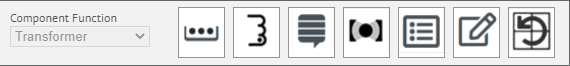
Following buttons are available in the header of the mechanical diagram block:
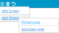
Add - user can add user shields and need to specify user shield parameters:
Delete - available only for shields. User can delete shield if necessary.
Reset Construction - Transformer Construction is reset to default
Winding info
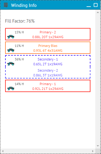
The winding information block displays the general parameters of the windings like number of turns, number of filars, wire size, number of layers, winding direction,
bobbin fill factor and winding to bobbin height ratio.
by clicking on particular winding in Winding Info block.
Electrical diagram
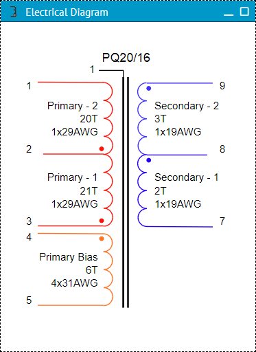
Electrical diagram provides the electrical scheme of the transformer. It displays electrical connections of the windings, pins allocation , polarity, external core
connection and general parameters of the windings. User can select winding to edit it's parameters by clicking on a particular winding on Electrical diagram block.
Core/Coil Former Parameters
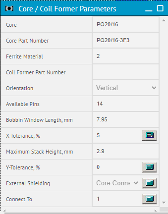
Core/Coil Former Parameters displays the parameters of the core and coil former and allows user to modify them by clicking on ![]() icon.
icon.
Core - core type.
Core part number - manufacturer's core part number
Ferrite Material - core material type
Coil Former Part Number - manufacturer’s coil former part number
Orientation - vertical or horizontal orientation of the coil former
Available pins - total number of pins available in current coil former.
Bobbin window length, mm - winding window length
X-tolerance, % - bobbin tolerance along the x-axis. User can specify from -7% to 7%.Mechanical diagram proportions will be recalculated accordingly.
Maximum stack height, mm - the maximum height of the window for all windings
Y-Tolerance, % - bobbin tolerance along the y-axis. User can specify from -7% to 7%.Mechanical diagram proportions will be recalculated accordingly.
External Shielding - contains three options:
None - without external shielding.
Flux Band - the flux band acts as a shorted turn for stray flux outside the magnetic circuit formed by transformer windings and the core. Stray magnetic field around the transformer
can interfere with adjacent circuitry and contribute to EMI. The flux band can also be connected to a stable DC node to help reduce electrostatically coupled interference.
Care should be taken to maintain the required creepage between primary and secondary windings of the transformer.
Core Connection - core is electrically connected to a pin selected by user (connect to) using wire.
Winding Parameters
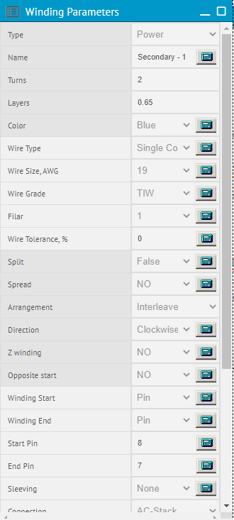
The winding parameters block contains all parameters of the selected winding. User can change parameters by clicking on ![]() icon and they will be immediately applied to the design.
icon and they will be immediately applied to the design.
Winding Properties:
Type - winding type: Power - primary or secondary power winding, Bias - a control winding that carries a steady direct current which serves to establish desired operating conditions in a magnetic amplifier or other magnetic device. Sometimes used as a feedback winding. Shield - the purpose of shield windings is to reduce capacitive coupling from primary windings
to secondary windings. Screen - one turn of foil to reduce interference. Screen prevents RF interference on the mains from being capacitively coupled to the circuitry.
Name - the name of the winding. By default, the windings are named according to their type. User can change the name of the winding.
Turns - number of winding turns.
Layers - number of winding layers.
Color - is used to differentiate windings by type. User can change the color of the winding.
Wire type - type of wire used in the winding. Contains the following types: Single core wire, Foil, Litz wire.
Wire Size, AWG - size of wire used in the winding
Filar - number of parallel wires used for winding.
Wire Tolerance - Wire Size Tolerance. Automatically recalculates the circle diameters on the mechanical diagram.
For Foil wire type:
Foil Thickness - thickness of copper foil used in the winding.
Overlap - overlap percentage of last foil layer.
For Litz wire type:
Single strand Wire Size - size of the single strand in litz wire.
Number of strands - number of single strands in litz wire.
Litz wire grade - type of litz wire insulation (Serve, Unserved,Triple insulated).
Split - winding can be splitted into 2 parts: False - no split required, Series - winding is splitted into 2 equal parts (turns and layers are evenly splitted). Splitted parts of the winding are electrically stacked. User can change the distribution of turns in both parts. Parallel - add the second part of the winding which replicates the first one. Both parts are connected to the same pins.
Continuous Pin - applicable only for series split. Termination lead of the first part of splitted winding is left unconnected. Second part starts winding with the same wire.
Spread - the turns on the last layer are evenly spread over the entire bobbin window length. If the last layer of the winding is not completely filled, then the user can choose to spread turns.
Arrangement - winding arrangement (independent, interleave, complimentary)
Direction - winding direction (clockwise, counterclockwise)
Z-winding - winding technique where each layer starts from one side
Opposite start - user can choose to start the winding from the opposite side, regardless of start pin side.
Winding Start - user can select the following options for the start lead of the winding:
Pin, Not connected, Flying Lead Left, Flying Lead Right.
Winding End - user can select the following options for the finish lead of the winding:
Pin, Not connected, Flying Lead Left, Flying Lead Right, Outlet on top left, Outlet on top right.
Start Pin - start pin name
End Pin - termination pin name.
Sleeving - insulation around wires, where they exit from the bobbin. User can choose to sleeve start lead, end lead or both.
Connection - type of electrical connection, shown in the electrical diagram. Floating - Parallel Winding, AC stack - windings connected into stack, Split - splitted windings.
Margin left, mm - safety margin on the left between coil former and winding
Margin right, mm - safety margin on the right between coil former and winding
Tape between layers - insulation layer between winding layers
Tape between lead & winding - insulation between winding layer and flying lead stretched from winding to the pin
Tapes of top on the lead of top - number of insulation tape layers over Outlet on Top connection
Tape on top - number of insulation tape layers on top of the winding
Tape Thickness - insulation tape thickness
Building instruction block
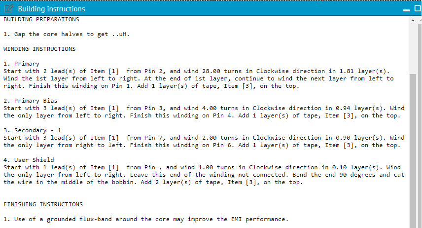
Building Instructions block contains instructions for building the transformer. It contains a complete list of materials used in transformer construction, building preparation instructions and measurements,
detailed step-by-step instructions for each winding, finishing instructions, and an electrical test specification for the finished transformer. User can edit automatically generated instructions and add comments.