The secondary divider is used by InnoSwitch3 for output regulation and completely eliminates the need for an optocoupler for output isolation. This solution is very low cost and highly accurate.
The feedback (FB) pin of the InnoSwitch3 device uses an AC coupled signal through a voltage divider to sense the output voltage and thus regulate the output.
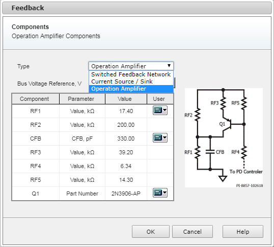
The different feedback networks are available to select by the dropdown menu “Feedback network type”
• Switched Feedback Network
• Current Source/Sink
• Operation Amplifier
The choice of which network to apply is highly dependent on the type of application and by the capability of the adopted PD controller.
The value defines the bus voltage for which the main voltage divider is designed to set.
| Feedback network type | Default value |
| Switched Feedback Network | Min set-point voltage |
| Current Source/Sink | Nominal Set-point voltage |
| Operation Amplifier | Max Set-Point voltage |
This drop down menu is enabled only when Custom Charger application is selected. In this case the user can select from all the set point’s voltages.
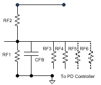
The PD Controller regulates the Power Supply output voltage by inserting one of the available resistors in parallel to the lower resistor (RF1) of the main Voltage divider. With this solution, the maximum number of resistors needed to cover the requested voltage range is equal to the number of set point minus one.
This feedback network can only increase the bus voltage; therefore, the value of RF1 is calculated accordingly to obtain the lowest set-point’s voltage on the positive rail
The default value of the upper resistor (RF2) is set to 200 kΩ. The user can manually overwrite its value which in turn will modify the value of the parallel resistors.
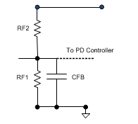
The PD Controller is able to both inject and draw current from the FB connection pin. This action virtually alters the relation between the upper (RF2) and lower (RF1) resistor of the main voltage divider and in fact cause the bus voltage to change.
Due to the capability to inject and draw current, this method can both increase and decrease the bus voltage.
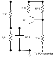
The PD Controller has internally an operation amplifier which drives a PNP transistor. When the transistor is conducting a current is injected in the FB pin connection which virtually modifies the ratio between RF1 and RF2 and therefore decrease the bus voltage.
This method is only able to inject current into the FB pin connection therefore it can only decrease the bus voltage.