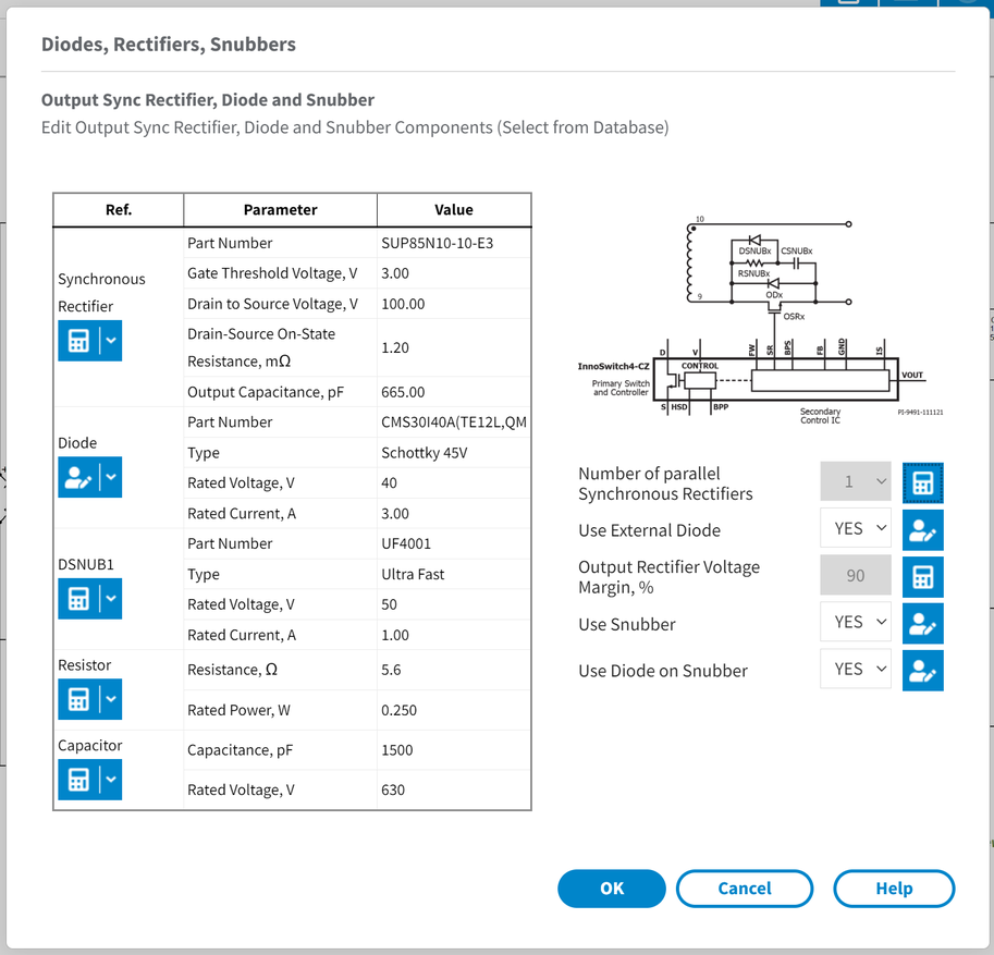
Use the Output Diodes,Rectifiers,Snubbers form to edit the output diodes, synchronous rectifiers and snubbers used in the current design.
PI Expert selects the output components when optimizing a design and ensures that the output diodes, snubbers and rectifiers parameters meet the specification.
You can replace the automatically chosen components by selecting another one from the database by clicking on the down blue arrow right of the calculator  and click Change.
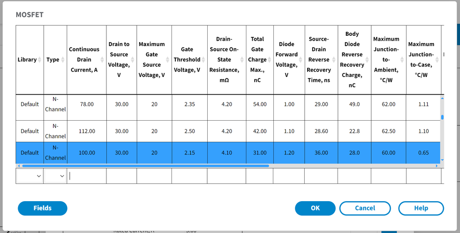
In the database window you can filter displayed parameters by clicking on the Fields button  . Check or uncheck boxes to display parameters or hide it. Select the necessary sync rectifier and click OK. Click on a user icon
  to toggle between default and user entered components.
RC snubbers are commonly placed across secondary and bias diodes. The primary function of the snubber circuit is to limit the peak voltage at the instant when the diode turns off and to reduce the ringing.
The snubber capacitance should normally be chosen, so that it is much larger than the rectifier capacitance at the expected peak inverse voltage.
Number of parallel synchronous rectifiers - number of synchronous rectifiers on output placed in parallel.
Use external diode - user can choose to use external diode in parallel with sync rectifier.
Output rectifier voltage margin, % - User can change output rectifier voltage margin value in percentage.
Use snubber - User can choose to use snubber on the output rectifier.
Use diode on snubber - User can choose to use diode in parallel with snubber resistor.