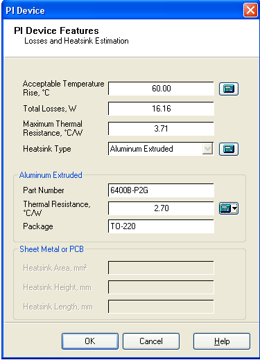
The Heatsink design form is used to calculate the parameters for components that remove unwanted heat from a device to keep it from overheating.

PI Expert calculates the components set automatically. You can manually change the temperature limit by editing the value in Acceptable Temperature Rise box. To edit the temperature click the calculator icon ![]() on the right of the parameter box. The
on the right of the parameter box. The ![]() icon indicates that a custom parameter value has been entered.
icon indicates that a custom parameter value has been entered.
The Heatsink Type is re-calculated automatically depending on the acceptable temperature value. You can select another heatsink type by click the calculator icon ![]() on the right of the Heatsink Type box. The available heatsink types are Copper PCB, Aluminum Extruded, Custom Aluminum and Custom Zinc Plated Steel.
on the right of the Heatsink Type box. The available heatsink types are Copper PCB, Aluminum Extruded, Custom Aluminum and Custom Zinc Plated Steel.
For each heatsink type the parameters are displayed in the bottom part of the Heatsink design form. When you have the Aluminum Extruded type selected you can change the thermal resistance. To do this in the Thermal Resistance box click the black down arrow control on the right of the calculator icon ![]() and select Change. In the Heatsink dialog box, select the component you want to add. Click OK. The
and select Change. In the Heatsink dialog box, select the component you want to add. Click OK. The ![]() icon indicates that the custom selected resistance is chosen. To restore the default resistance click the black down arrow control on the right of the
icon indicates that the custom selected resistance is chosen. To restore the default resistance click the black down arrow control on the right of the ![]() icon and click Default.
icon and click Default.
For Custom Aluminum and Custom Zinc Plated Steel types you can change the heatsink height value. To do this click the calculator icon ![]() on the right of the Heatsink Height box. Edit the parameter value. The
on the right of the Heatsink Height box. Edit the parameter value. The ![]() icon indicates that a custom parameter value has been entered. To restore the default value click the
icon indicates that a custom parameter value has been entered. To restore the default value click the ![]() icon.
icon.
There are three types of heatsinks supported by PI Expert:
External aluminum-extruded heatsinks
External custom aluminum or zinc-plated steel heatsinks
PCB copper area used for heatsinking
The first two options employ the use of a separate heatsink element. Be it a custom made heatsink (where the size and the shape of the heatsink are customized and cut for the design) or a standard off-the-shelf extruded heatsink, which are typically used with the Y (TO-220) or E (eSIP-7C) packages. While the effectiveness of a heatsink (thermal resistance) is primarily a function of the exposed surface area, the thickness of the heatsink also lays an important role. Typically a thicker heatsink with dimensions L x H has slightly better (lower) thermal resistance than a less thick heatsink with similar dimensions.

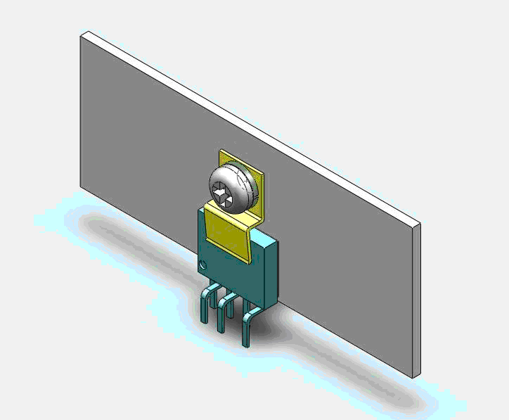
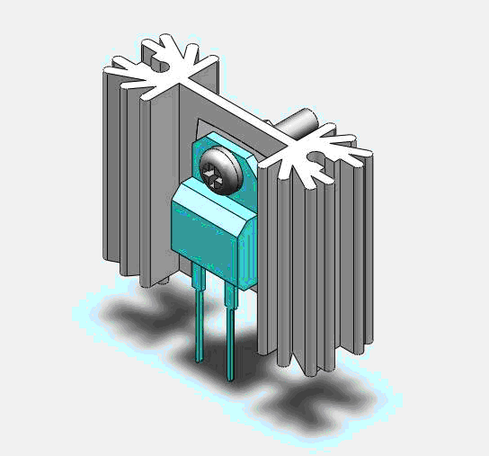
The figure above shows an eSIP-7C package attached to a custom (sheet metal) heatsink with the help of a screw clip. PI Expert helps to calculate the surface area of such a heatsink. Similarly, the figure below shows a diode in a TO-220 package that is attached to an extruded aluminum heatsink.

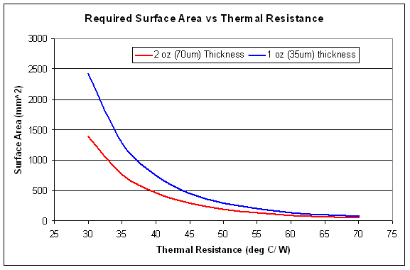
For the DIP or SO8 packages, the copper area on the PCB can be used for heatsinking. The advantage of this method is that there is no additional external heatsinking component required. Obviously, the thickness of the copper on the PCB determines the area required for heatsinking. The recommendations for PCB area assume a square area for heatsinking, so depending on the shape of the heatsink the thermal resistance may vary.
