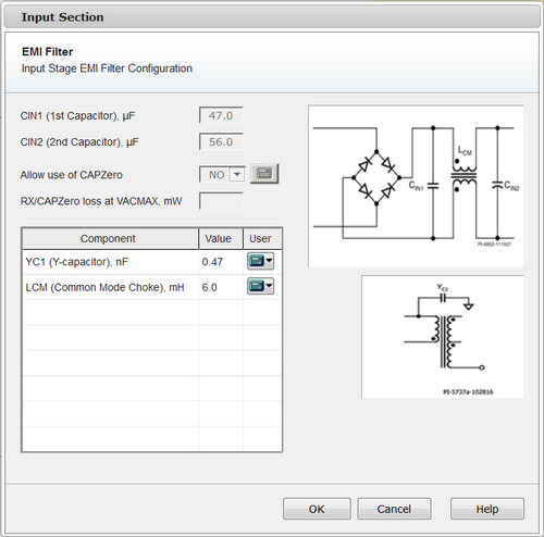
Use the EMI Filter form to review and edit the EMI circuit configuration.

PI Expert provides a starting base for a conducted EMI filter. There are five different EMI circuits that PI Expert uses. PI Expert selects the most appropriate filter circuit based on the output power and the type of application. For non-LED applications with standard bulk capacitors the following filters are automatically selected:
Lower than 3 W: a simple π (pi) filter arrangement is used. PI Expert separates the input capacitance into two capacitors (CIN1, CIN2) with equivalent capacitance that is greater than or equal to the minimum input capacitance (CMIN). An appropriate inductor (L1) is then inserted between the two capacitors in the DC plus rail.
Between 3 W and 5 W: PI Expert uses a π (pi) filter arrangement similar to the one above only with an inductor (L2) in the DC return in addition to the DC plus rail.
Between 5W and 10 W: a further modification to the π (pi) filter previously used is made whereby a resistor (R1) is placed in parallel with the inductance present in the return rail.
Between 10 W and 20 W: a common mode choke (LCM) is used in a π (pi) filter-like arrangement inserted between the two bulk capacitors (CIN1, CIN2).
Greater than 20 W: an X capacitor (CX) is placed between Line and Neutral which then has a common mode choke (LCM) placed before the bridge rectifier which feeds the bulk capacitor (CIN1).The default size of the X capacitor depends on the output power of the converter.
Greater than 27 W: the size of the default X capacitor becomes larger than 0.1uF. IEC950 standard requires that all capacitors larger than 0.1uF, which are connected to external mains, have a means of discharge for pluggable equipment of type A. PI Expert automatically adds resistors RX1 and RX2 to discharge the X capacitor and a CAPZero device to minimize their no-load power consumption. The dialog displays the worst case additional standby power dissipation from these components.
CAPZero:
A side effect of adding RX1 and RX2 resistors for X capacitor discharge is a small amount of additional power dissipation, which degrades no load power consumption. CAPZero is a specialized Automatic X Capacitor Discharge IC to dramatically reduce dissipation from these resistors. If Allow use of CAPZero is set to YES, PI Expert automatically adds a CAPZero device to the circuit when appropriate. To help evaluate the impact of adding CAPZero, the dialog displays the worst case standby power dissipation of RX1+RX2 resistors or RX1+RX2+CAPZero, calculated at maximum line voltage.
For LED applications, the following filters are used:
Lower than 8W: 2 LC filters are used after the rectifier. The input capacitance is divided into two capacitors (CIN1, CIN2). Two inductors (EMI_L3 and EMI_L4) are then used to make the LC arrangement on the positive rail.
Between 8W and 40W: An X-Capacitor is used (EMI_CX), and two Inductors are added on the AC side (EMI_L1, and EMI_L2). On the rectified side a single LC filter is used (EMI_L3 + CIN).
Greater than 40W: In addition to the components used for an output power between 8W and 40W, a common mode choke is added on the AC side (EMI_LCM)
PI Expert appropriately calculates and incorporates discharge resistors across X capacitors to ensure compliance with safety agency requirements
Note: The EMI circuit topology and component values given are a starting point for conducted EMI filters. Often empirical testing of filter components and topologies is necessary to meet the specifications with adequate margins.
To change a component of the EMI filter click the black down arrow control on the right of the calculator icon ![]() and select Change.
and select Change.
The dialog boxes where you can select another component will be displayed as the following:
The Differential Choke dialog box - for the inductor
The Capacitor dialog box - for the capacitor
The Resistor dialog box - for the resistor
Select the component you want to add, or edit the resistor parameters when changing the resistor. Click OK.
The component is now replaced. The ![]() icon indicates that the custom selected diode is chosen. To restore the default component click the black down arrow control on the right of the
icon indicates that the custom selected diode is chosen. To restore the default component click the black down arrow control on the right of the ![]() icon and click Default.
icon and click Default.