The bus switch circuitry provides a safe electrical disconnection between the load and power supply when the Vbus needs to change from a higher to a lower voltage value or vice versa.
The disconnection can be realized with either one single MOSFET or two series MOSFETS connected in back to back configuration.
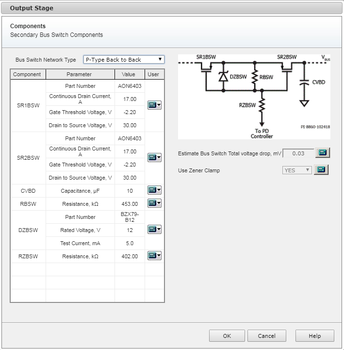
The drop down menu “bus switch network type” provides the user with 4 different options.
N-type single
P-Type single
N-Type back to back
P-Type back to back
This is the simplest configuration. The electrical disconnection is realized by switching off the single N-Channel (P-Channel) MOSFET.
N.B. Due to the presence of the MOSFET’s body diode, a inrush current is allowed to flow from the load to the power supply if the load voltage happens to be higher that the bus voltage.
Two N-Channel (P-Channels) MOSFET are connected in series in back to back configuration. This allow to realize an ”ideal” disconnection. Using a back to back configuration the MOSFETs’ body diodes face are orientated in opposite direction not allowing the current to flow.
PI Expert allows the user to enter the target voltage drop across the MOSFET (s).
In order to satisfy the total voltage drop target, PI Expert selects the MOSFET(s) with the appropriate RDSON.
When the user a back to back configuration the total voltage drop target is series of the voltage drop of the two single MOSFETs.
The default value is 30mV although the user is free to manually modify it by clicking on the icon ![]() next to the field..
next to the field..
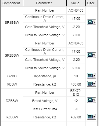
The component table shows the selected components. The user can overwrite each selection by clinking on the icon ![]() . This will open the specific component database library where the user can search for another existing record.
. This will open the specific component database library where the user can search for another existing record.